




Sauna air outlet
Sauna air outlet is an opening or terminal intended to carry air out of a sauna room. The air may transfer to an adjoining room, enter a return or extract duct, or follow a system that eventually discharges it outdoors. These destinations are not equivalent. An opening's label and height do not demonstrate its actual direction, volume flow or effect at the benches.
Outlet performance depends on the complete ventilation path: the Sauna air inlet, pressure in connected spaces, fans, heater and chimney where present, terminal and duct resistance, leakage, and the operating state. This makes outlet design a system question as well as a component question.[1]
Room extract, transfer and final exhaust
Extract air has crossed out of a room; exhaust air has been discharged from the building. Transfer air crosses between rooms and may subsequently be extracted somewhere else. Finland's Decree 1009/2017 defines these boundaries, classifies extract air by the impurities it may contain, and regulates transfer and recirculation for building work within its Finnish scope.[2] Thus, a low opening to a washroom may be the sauna-room outlet while the building's final exhaust is a fan and terminal elsewhere.

The destination should be explicit. Air released into an unintended wall, ceiling or floor void is not a valid transfer arrangement merely because it leaves the visible room. Heat and moisture entering an unexamined cavity can create concealed condensation and damage to the construction. A designed transfer route instead includes the receiving space and downstream extract in its pressure and moisture balance.
Pressure, resistance and flow direction
Sustained net outflow requires replacement inflow. In an extract-only system, a fan creates depression and replacement air divides among intended openings and leakage paths. A passive outlet responds to wind and temperature-related pressure differences as well as to fans or doors elsewhere in the building. Chimney draught can also shift the indoor pressure field. Any of these changes can reduce or reverse flow through the nominal outlet.
The terminal's capacity is governed by pressure difference and effective flow resistance. Grilles, dampers, screens, ducts and bends matter; nominal diameter by itself is not a flow rating. Likewise, a local velocity at one point is not outlet volume flow. A measured outlet flow is not automatically the room's air-change rate, because that calculation also requires a declared room volume and boundary, while leakage and transfer routes may carry part of the exchange.
An operating record should distinguish closed-door warm-up, occupied bathing, adjoining-fan operation and drying. Opening the whole door creates a relatively large, transient and potentially two-way exchange. A direction observed with the door closed and fans steady cannot simply be assigned to the door-open state.
Placement and room distribution
Outlet flow and internal distribution answer different questions. A substantial flow can pass directly from supply to extract while leaving parts of the room weakly served; conversely, a remote outlet can pass little air if the available pressure is inadequate. The heater plume, supply-jet momentum, surfaces and people contribute to airflow within the sauna. High and low outlets encounter different regions of a stratified room but do not, by position alone, create a particular temperature or guarantee contaminant removal.

The principal sauna-specific experiment was narrow. Äikäs and Holmberg studied one electrically heated test sauna with mechanical exhaust. With incoming air introduced above the heater, placing the extract low promoted mixing between the upper and lower parts of that room.[3] Fan, Holmberg and Heikkinen then modelled two inlet arrangements in the same two-metre-cube room and found corresponding changes in its temperature and flow fields.[4] Neither work compared natural, balanced, supply-only and combustion-dependent rooms, so the low-extract result is not a universal prescription.
Documented outlet arrangements
Manufacturer instructions illustrate why system context cannot be removed from a placement rule. Harvia describes low remote outlets for several electric and mechanically extracted configurations. Its wood-burning gravity example instead places a remote opening high in the room and describes its principal purpose as removal of humidity after bathing.[5] Tylö specifies a high remote self-draught return to the same adjoining pressure space as its inlet for the product concept in its building guide.[6]
-
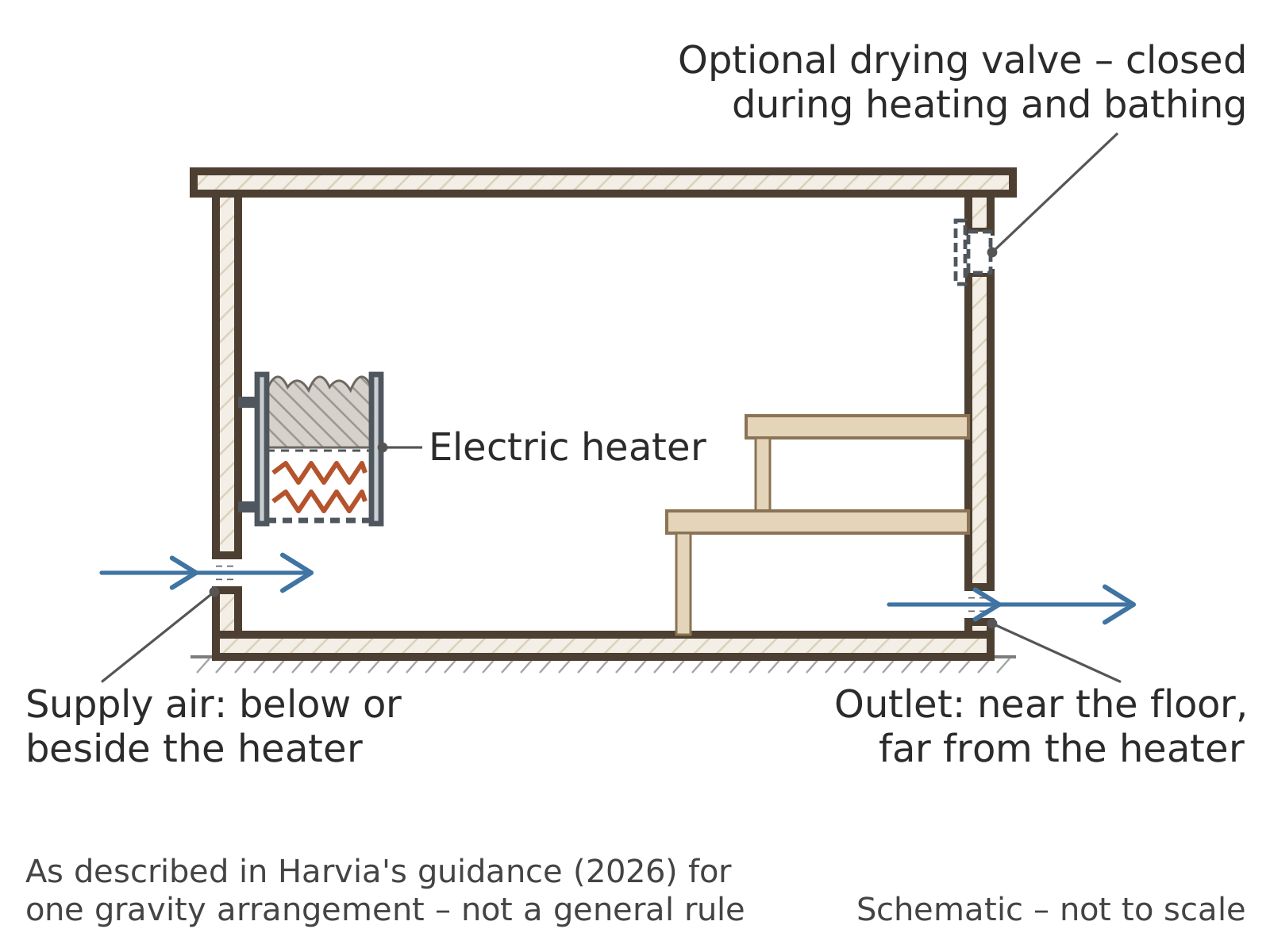 Electric heater, gravity arrangement as described by Harvia: outlet low and remote from the heater.
-
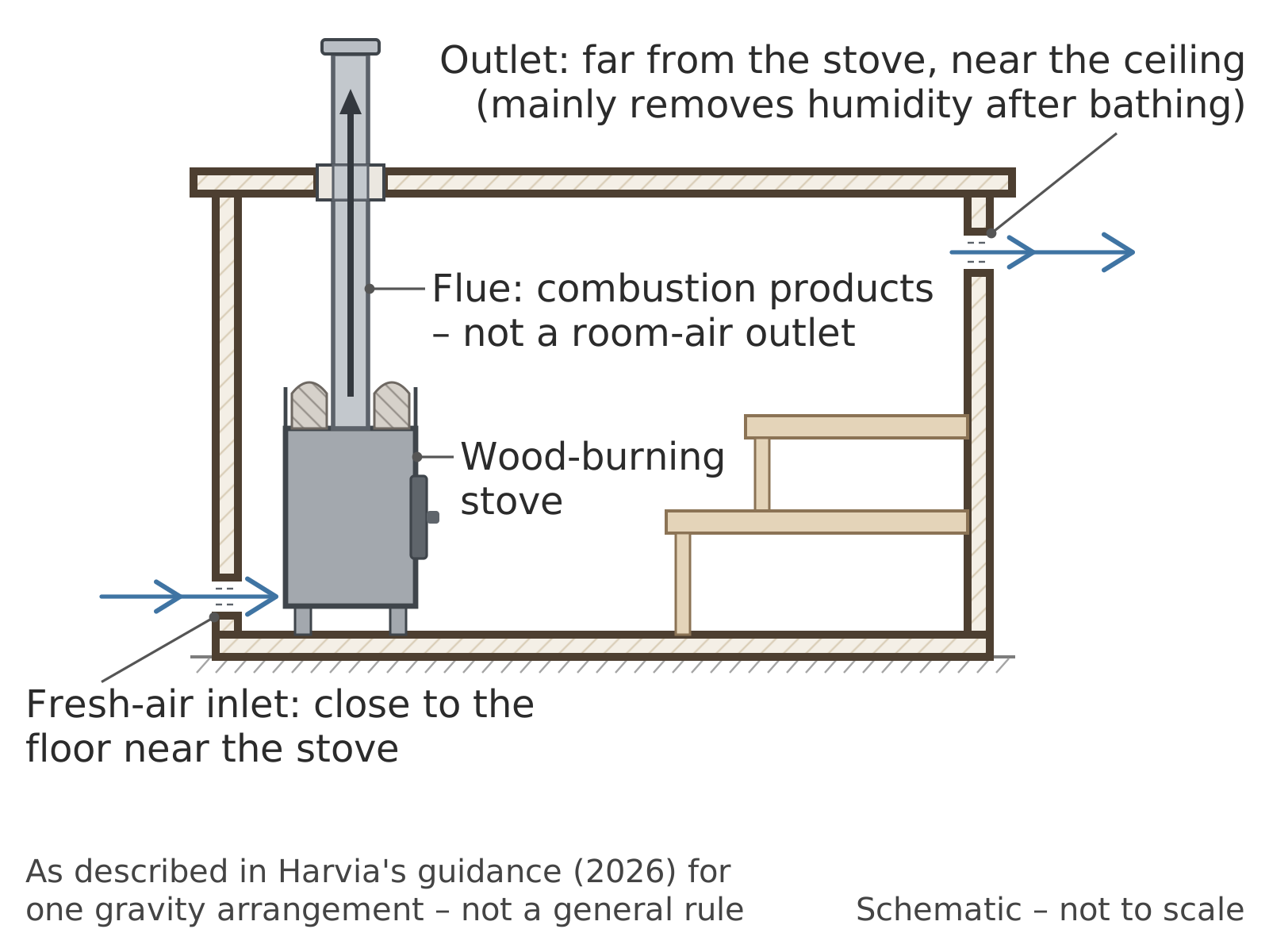 Wood-burning stove, gravity arrangement as described by Harvia: remote opening high in the room, mainly for removing humidity after bathing. The flue is not a room-air outlet.
-
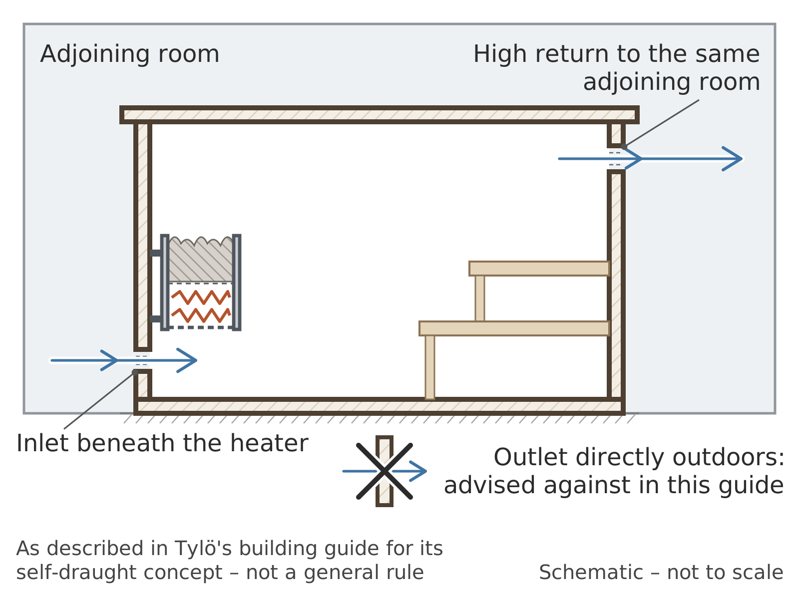 Self-draught arrangement as described by Tylö: inlet under the heater, high return to the same adjoining room, not outdoors.


These documents are primary product guidance, not trials establishing relative performance. Harvia's dimensions or drying sequence cannot be merged with Tylö's pressure path, nor transferred to a different heater without evidence of compatibility. Natural sauna ventilation and Mechanical sauna ventilation impose different drivers, but neither system name decides outlet height independently of the rest of the installation.
A gap beneath the sauna door may carry air outwards as part of a transfer route to washroom extract. The same opening may act as an inlet when the pressure is reversed. Its geometry also forms part of the doorset: ventilation changes must not disregard accessibility, fire, threshold or safe-opening requirements in the overall design.
Bathing, drying and outdoor discharge
Some installations use one outlet during occupation and a separate high opening for drying. Product instructions may require the drying opening to remain closed during heating and bathing and to be opened afterwards; another documented method uses an open door after the session.[5] These are prescribed modes for particular systems, not general sauna etiquette. Detailed drying sequences belong to Ventilating a sauna after use.
Drying is governed by moisture mass flow, surface moisture, temperature, residual heat and time. Relative humidity at one terminal does not by itself quantify the water removed. In a VTT study of Helsinki swimming-pool and apartment-building sauna facilities, enhanced ventilation together with residual heater heat was necessary for drying, and mechanical supply-and-extract performed best among the arrangements examined.[7] That facility study did not establish a single outlet location or drying time for domestic rooms.
Final outdoor discharge introduces another boundary. Its location should limit re-entrainment into air intakes and avoid nuisance; wind and the façade or roof geometry affect the result. Rain, snow and condensate can impair terminals or ducts. Exact separation and weathering requirements are jurisdiction-specific. Where air passes through heat-recovery equipment, frost, moisture, bypass operation and leakage between streams require analysis at system level rather than at the sauna grille alone. The public scope of EN 16798-3:2025 principally covers mechanical ventilation and room-conditioning systems in non-residential buildings and supplies no universal sauna outlet location.[8]
Measurement and maintenance
ISO 16956:2015 covers field airflow measurement in steadily operating ducts and at air-control ports, including suction and exhaust openings.[9] ASHRAE Standard 41.2-2026 addresses air-velocity and airflow measurement, including density effects. Standard 111-2024 covers field measurement, adjustment and balancing of building HVAC systems, including room pressurisation and room air-change rates.[10] These standards describe measurement scopes, not sauna outlet positions.
Tracer-gas testing under ISO 12569:2017 can estimate ventilation for a qualifying single zone when its conditions concerning mixing, fluctuation and exhaust sampling are satisfied. ISO 9972:2015 instead measures envelope air permeability under imposed fan pressure and does not evaluate individual components.[11] Strong stratification or short-circuiting can make one exhaust sample unrepresentative. A sound test record identifies fan and damper settings, door and heater states, temperatures, instrument limits and uncertainty.
Grilles, dampers and accessible duct sections should be checked for dust, damage, condensate and changes in setting. Blocking an outlet to retain heat can alter pressure, air quality and drying. A stove flue is not a room-air outlet: it carries combustion products under chimney draught. Mechanical extract can affect that draught, and extra room ventilation is not a remedy for incomplete combustion or a defective flue.[12] Combustion safety and indoor air quality require source control as well as an intact ventilation route.
See also
References
- ↑ ASHRAE, “Ventilation and Infiltration”, chapter 16, 2025 ASHRAE Handbook—Fundamentals, 2025, official online chapter, accessed 5 September 2026.
- ↑ Finland, Ministry of the Environment, Decree 1009/2017 on the Indoor Climate and Ventilation of New Buildings, issued 20 December 2017, Finlex record, accessed 5 September 2026.
- ↑ Erkki Äikäs and Rolf Holmberg, Saunan lämpötilat ja ilmanvaihto [Temperature and ventilation of the Finnish sauna], VTT Research Notes 1431, VTT Technical Research Centre of Finland, Espoo, 1992, 40 pp., ISBN 951-38-4325-4, official record, accessed 5 September 2026.
- ↑ Youchen Fan, Rolf Holmberg and Jorma Heikkinen, “CFD simulation on the air flow in a sauna: Fresh air inlet position influences air flow and temperature distribution whilst radiant heat emission takes about 75% of total stove heat output”, Building Research & Information, volume 22, number 6, 1994, pp. 307–312. doi:10.1080/09613219408727409.
- ↑ 5.0 5.1 Harvia, “Ventilation in the sauna”, updated 29 January 2026, official support page, accessed 5 September 2026.
- ↑ Tylö, How to Build a Sauna, hosted edition created May 2025, pp. 4–6, official PDF, accessed 5 September 2026.
- ↑ Mikko Saari, Marja-Liisa Pallari, Mikael Salonvaara, Hannu Kääriäinen, Hannu Viitanen, Iris Humala, Sari Liski-Markkanen, Anne Malin and Kirsi Laitinen, Terveen saunan tekijät [Elements of healthy sauna], VTT Research Notes 2144, VTT Technical Research Centre of Finland, Espoo, 2002, 111 pp., ISBN 951-38-5899-5 and 951-38-6049-3, official record, accessed 5 September 2026.
- ↑ European Committee for Standardization, EN 16798-3:2025, Energy performance of buildings — Ventilation for buildings — Part 3: For non-residential buildings — Performance requirements for ventilation and room-conditioning systems, 2025, official EVS adoption record, accessed 5 September 2026.
- ↑ International Organization for Standardization, ISO 16956:2015, Thermal performance in the built environment — Determination of air flow rate in building applications by field measuring methods, first edition, confirmed 2025, official record, accessed 5 September 2026.
- ↑ ASHRAE, Standard 41.2-2026, Standard Methods for Air Velocity and Airflow Measurement, 2026, and Standard 111-2024, Measurement, Testing, Adjusting and Balancing of Building Heating, Ventilation and Air-Conditioning Systems, 2024, official titles, purposes and scopes, accessed 5 September 2026.
- ↑ International Organization for Standardization, ISO 12569:2017, Thermal performance of buildings and materials — Determination of specific airflow rate in buildings — Tracer gas dilution method, third edition, confirmed 2024, official record; and ISO 9972:2015, Thermal performance of buildings — Determination of air permeability of buildings — Fan pressurization method, third edition, confirmed 2026, official record, accessed 5 September 2026.
- ↑ Tina Chen, “Rapid review: Environmental health risks and safety considerations in saunas”, National Collaborating Centre for Environmental Health, 16 January 2026, official evidence brief, accessed 5 September 2026.