




Natural sauna ventilation
Natural sauna ventilation is intentional air exchange in which wind and temperature-related pressure differences, rather than a supply or extract fan, are the principal driving forces. The term is also used for gravity, passive or self-draught systems, although usage is not completely uniform. A natural system requires connected openings and pressure differences across them. Heater-driven circulation inside a closed room can be vigorous without bringing in outdoor air.[1]
Pressure field
Different indoor and outdoor air densities create a height-dependent pressure difference. Wind produces another distribution of positive and negative pressures over walls and roofs. Both effects act through the same indoor pressure field; their flows cannot simply be calculated separately and added. Building form, surrounding obstructions, opening resistance and leakage distribution therefore influence both direction and quantity.[1]

The neutral-pressure level is the height at which indoor and outdoor static pressures are equal for a particular state. It can move when a door opens, a chimney operates, wind changes, or a fan in an adjoining room starts. An opening near this level may have little driving pressure. Greater height separation can increase the potential stack pressure, but does not guarantee a useful flow if the openings or connecting route have high resistance.
Finland's Decree 1009/2017 defines a natural-draught ventilation system as one whose operation is based principally on pressure differences caused by height, temperature and wind.[2] That legal definition applies to the decree's Finnish new-building and extension scope; it does not make the remainder of the decree a worldwide sauna specification.
Planned air path
The Sauna air inlet and Sauna air outlet must connect suitable pressure spaces. Flow through each depends on its effective free area and discharge characteristics as well as the pressure difference. Grilles, insect screens, dampers, ducts and bends reduce effective capacity. Cracks may contribute infiltration, but their flow is uncontrolled and can oppose the intended route.
A gap beneath the door may carry transfer air between a hot room and an adjoining washroom. Direction is not inherent in the gap: an extract fan in either space, another open door or a chimney can reverse it. Opening the whole door creates a much larger, transient and commonly two-way exchange, not a steady enlargement of the under-door flow.
Net exchange is also different from internal airflow. A heater plume can create rapid recirculation while the net boundary flow remains small. Conversely, a measured terminal flow can short-circuit across part of the room and leave uneven conditions at the benches. The Sauna air change rate normalises a defined volume flow by a defined room volume; it does not reveal the route taken by the air.
Heater and building interaction
An electric heater adds buoyancy but consumes no combustion air. A wood-burning heater also draws combustion air and establishes chimney draught. The flue carries combustion products and is not a room-air exhaust terminal. Extract systems elsewhere in a dwelling can depressurise the sauna even when no fan is installed in the hot room. Once fan pressure materially drives the route, the installation is hybrid or mechanically influenced rather than purely natural. A general ventilation opening should not be assumed to satisfy a stove's combustion-air requirements.[3]
The principal direct sauna airflow studies do not test natural systems. VTT's 1992 experiment used mechanical exhaust in one electrically heated test sauna. It showed that cool supply air tended to descend unless it mixed with the heater-driven circulation.[4] Fan, Holmberg and Heikkinen modelled two inlet positions in that same approximately two-metre-cube, mechanically exhausted room.[5] Their findings are relevant to buoyancy and mixing, but do not validate a natural-ventilation layout.
Documented arrangements
Product instructions describe different natural routes because the heater and adjoining pressure space differ. Harvia's current guidance shows, for one gravity arrangement with an electric heater, supply below or beside the heater and an outlet low and remote. Its wood-burning example has low supply near the stove and a high remote opening used principally to remove moisture after bathing.[6]
-
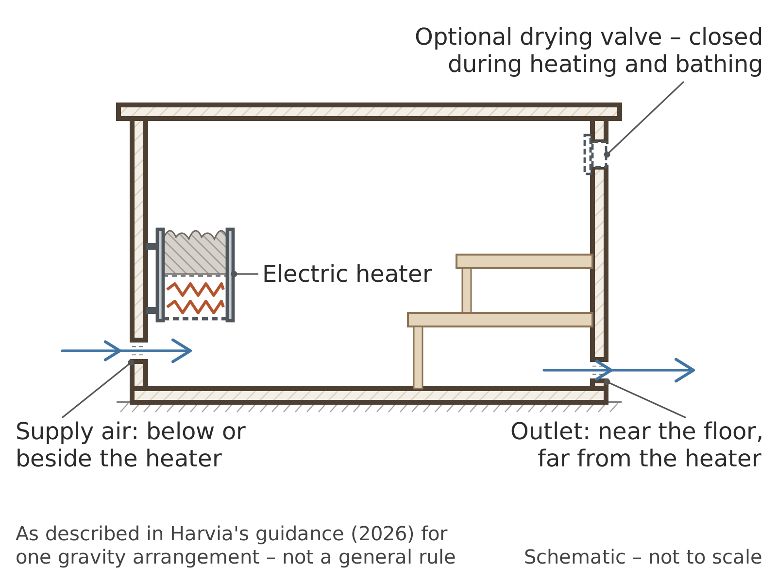 Gravity arrangement with an electric heater as described in Harvia's guidance: supply below or beside the heater, outlet near the floor and remote from it. One manufacturer's arrangement, not a general rule.
-
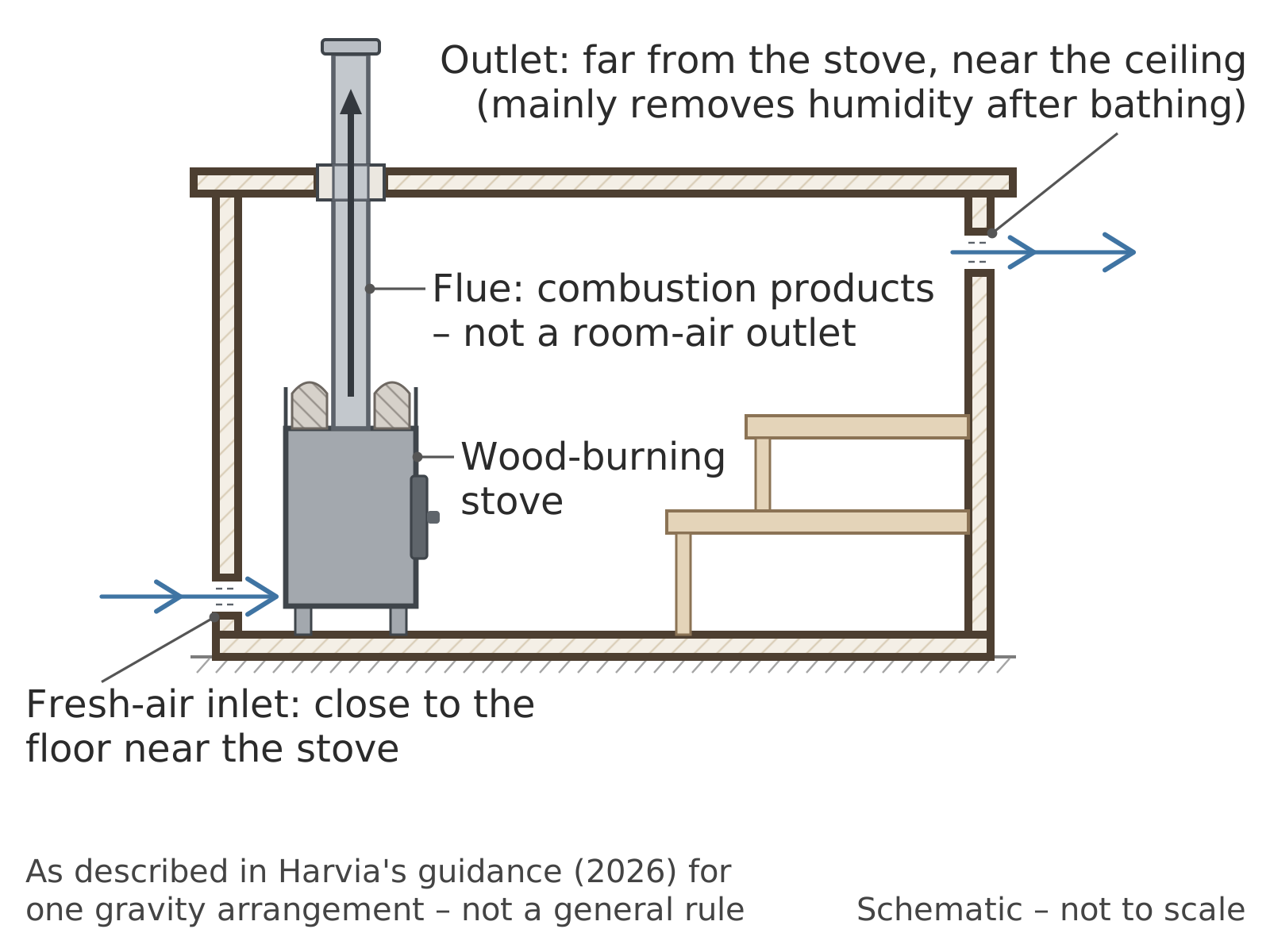 Gravity arrangement with a wood-burning stove as described in Harvia's guidance: low supply near the stove and a high remote opening used mainly to remove moisture after bathing. The flue is not a room-air outlet.
-
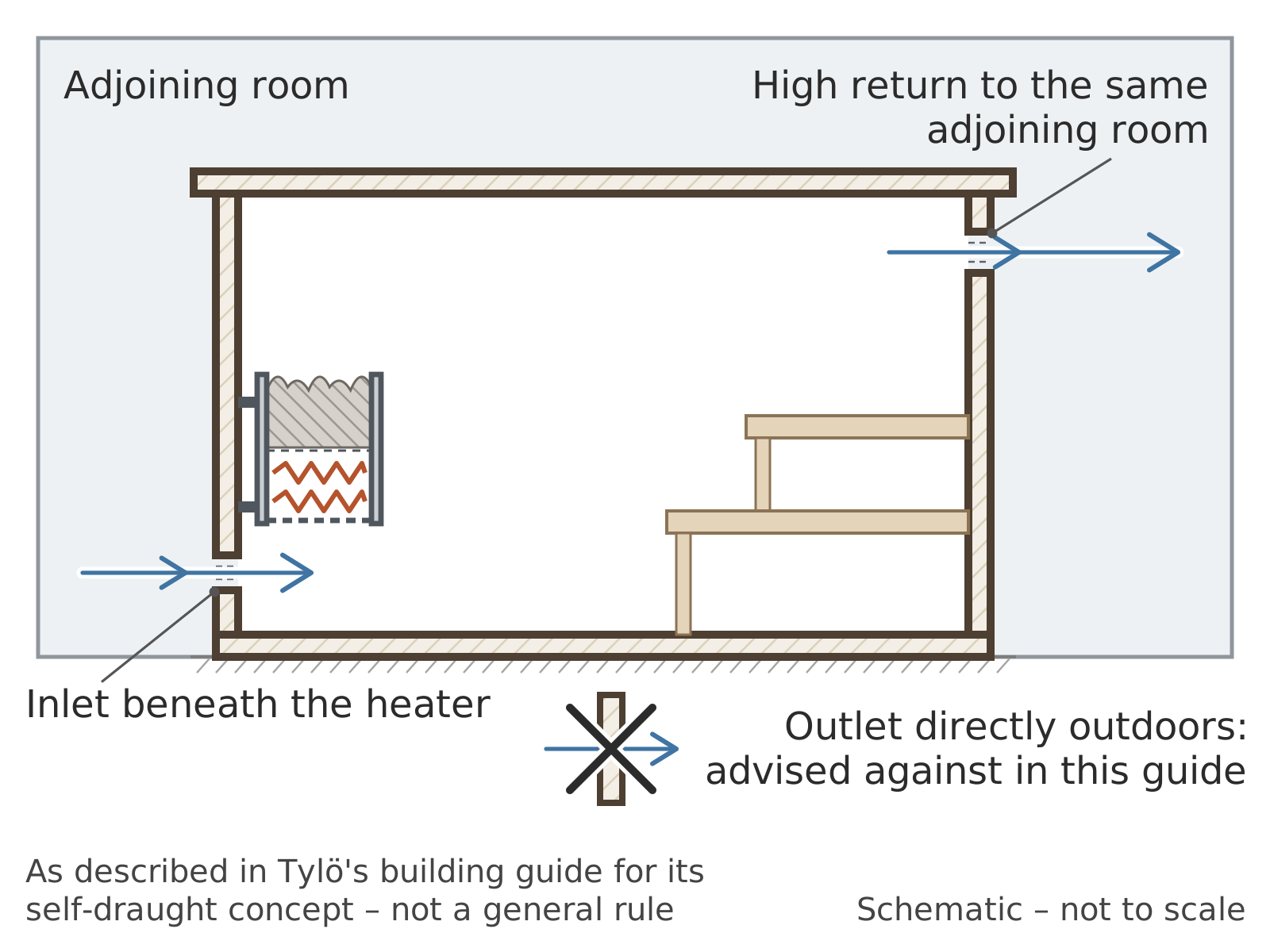 Self-draught arrangement as described in Tylö's building guide: inlet directly under the heater and a high return far from it, back to the same adjoining room rather than outdoors. One manufacturer's arrangement, not a general rule.


Tylö's guide specifies, for its own product concept, supply beneath the heater and a high remote return to the same adjoining pressure space. It warns that a direct outdoor outlet in that arrangement can reverse under wind or mechanical extraction in the building.[7] This is evidence about the named system, not proof that outdoor discharge is inherently wrong. Dimensions and positions from different manufacturers should not be averaged or combined; the Sauna design must follow the applicable heater instructions and actual pressure route.
Operation and drying
Warm-up, occupied bathing, water application and cooling continually change density and moisture. Calm mild weather may produce little natural pressure, while cold or windy conditions may produce a larger or reversed flow. A damper can have different settings for bathing and drying, but no universal “always open” or “always closed” instruction follows from the method itself.
Drying depends on water stored in surfaces, residual heat, incoming-air moisture, mass flow and time. In a 2002 VTT study of Helsinki public and apartment-building sauna facilities, enhanced ventilation with residual heater heat assisted drying, while mechanical supply-and-extract performed best among the installations studied.[8] The small Finnish sample does not show that every natural system dries poorly, nor does it provide a passive-vent schedule. Operating procedures are covered in Ventilating a sauna after use. Natural openings provide no inherent heat recovery, and low fan energy does not by itself demonstrate low total energy use.
Evaluation and measurement
An evaluation should cover the weather and operating states relevant to the installation. ISO 16956:2015 provides field methods for measuring airflow through ducts and terminals under steady operation.[9] Very small or fluctuating natural flows may fall outside an instrument's reliable range, and a capture hood can disturb the pressure that drives the opening.
A one-time check cannot characterise a weather-driven system. Observations should distinguish calm and windy conditions, warm-up and steady heating, closed and open doors, and the operation of extract fans or a stove. Direction indicators can reveal reversal, but do not quantify volume flow. Pressure readings across openings help explain direction only when their reference locations and instrument resolution are stated. Grilles, screens and dampers also require inspection: blockage changes resistance, while removing a screen to improve flow can compromise weather or insect protection. The intended position of every closable component should be documented for each operating mode. If acceptable performance depends on an unusually narrow weather condition, the remedy may require redesign or a controlled hybrid mode rather than an unrecorded user adjustment.
ISO 12569:2017 describes tracer-gas decay, continuous-dose and constant-concentration methods for a qualifying single zone.[10] Strong stratification, changing natural flow and inadequate sampling complicate interpretation. ISO 9972:2015 instead determines enclosure air permeability under imposed fan pressure; its result is not the natural exchange during bathing.[11]
Carbon-dioxide measurements can sometimes inform an occupancy-related assessment if generation, outdoor concentration, mixing, sensor position and time are known. They are not a complete measure of Indoor air quality in a sauna and do not certify combustion safety.[12] A useful record also gives opening and door states, weather, heater and chimney conditions, other fan operation, measurement uncertainty and observed direction.
EN 16798-3:2025 chiefly addresses mechanical supply and exhaust systems in non-residential buildings. Its public scope excludes residential systems and natural parts of hybrid systems.[13] It cannot support a universal passive opening size or location. No checked source establishes one natural inlet height, outlet height, opening ratio or rate for all saunas; assessment belongs within the complete construction and wider technical system.
See also
References
- ↑ 1.0 1.1 ASHRAE, “Ventilation and Infiltration”, chapter 16, 2025 ASHRAE Handbook—Fundamentals, 2025, official online chapter, accessed 5 September 2026.
- ↑ Finland, Ministry of the Environment, Decree 1009/2017 on the Indoor Climate and Ventilation of New Buildings, issued 20 December 2017, sections 1, 2, 8, 17, 21–22 and 27, Finlex record, accessed 5 September 2026.
- ↑ Tina Chen, “Rapid review: Environmental health risks and safety considerations in saunas”, National Collaborating Centre for Environmental Health, 16 January 2026, official evidence brief, accessed 5 September 2026.
- ↑ Erkki Äikäs and Rolf Holmberg, Saunan lämpötilat ja ilmanvaihto [Temperature and ventilation of the Finnish sauna], VTT Research Notes 1431, VTT, Espoo, 1992, 40 pp., ISBN 951-38-4325-4, official record, accessed 5 September 2026.
- ↑ Youchen Fan, Rolf Holmberg and Jorma Heikkinen, “CFD simulation on the air flow in a sauna”, Building Research & Information, volume 22, number 6, 1994, pp. 307–312. doi:10.1080/09613219408727409.
- ↑ Harvia, “Ventilation in the sauna”, updated 29 January 2026, official support page, accessed 5 September 2026.
- ↑ Tylö, Guide — How to build a sauna, current hosted edition, pp. 4–5, official PDF, accessed 5 September 2026.
- ↑ Mikko Saari et al., Terveen saunan tekijät [Elements of healthy sauna], VTT Research Notes 2144, VTT, Espoo, June 2002, 111 pp., ISBN 951-38-5899-5 and 951-38-6049-3, official record, accessed 5 September 2026.
- ↑ International Organization for Standardization, ISO 16956:2015, Thermal performance in the built environment — Determination of air flow rate in building applications by field measuring methods, edition 1, confirmed 2025, official record, accessed 5 September 2026.
- ↑ International Organization for Standardization, ISO 12569:2017, Thermal performance of buildings and materials — Determination of specific airflow rate in buildings — Tracer gas dilution method, edition 3, confirmed 2024, official record, accessed 5 September 2026.
- ↑ International Organization for Standardization, ISO 9972:2015, Thermal performance of buildings — Determination of air permeability of buildings — Fan pressurization method, edition 3, confirmed July 2026, official record, accessed 5 September 2026.
- ↑ ASHRAE, Position Document on Indoor Carbon Dioxide, revised 12 February 2025, official PDF, accessed 5 September 2026.
- ↑ European Committee for Standardization, EN 16798-3:2025, Energy performance of buildings — Ventilation for buildings — Part 3: For non-residential buildings, 2025, official EVS adoption record, accessed 5 September 2026.