




File:Sauna electrical installation scope conceptual diagram.svg
Sauna_electrical_installation_scope_conceptual_diagram.svg (SVG file, nominally 2,000 × 1,500 pixels, file size: 3 KB)
Summary
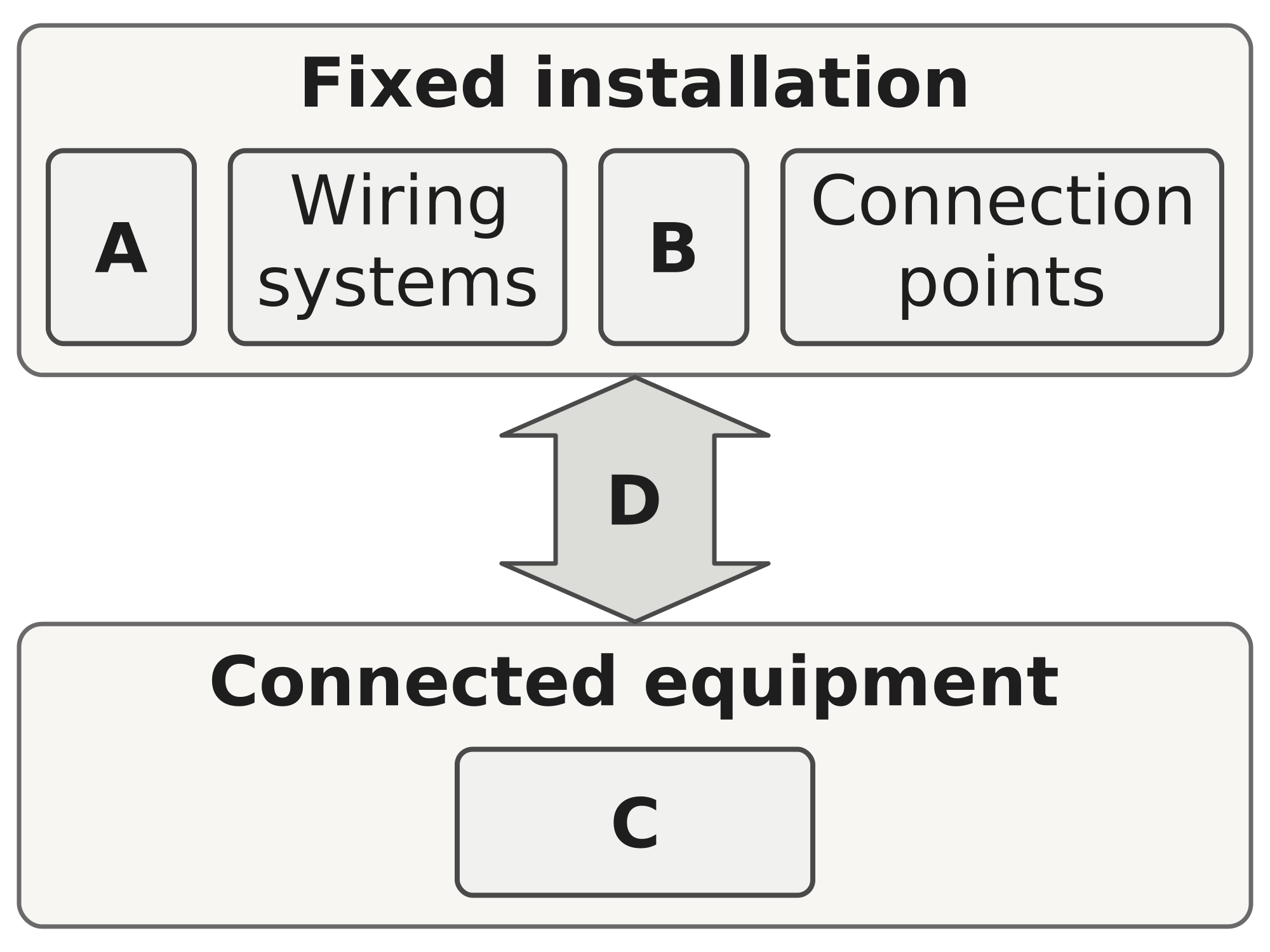
Two boundaries contain four fixed-installation groups and one equipment group, linked by a product-specific interface arrow.
Fixed-installation scope includes protection and switching, wiring systems, protective conductors and connection points. The protection group includes separate functions for isolation, switching, overcurrent protection and residual-current protection where required. One device can combine functions. Heater, control unit, sensors and lights are shown only as connected equipment. Neither the order of devices nor RCD allocation to any circuit is specified. Label key: A: Protection and switching. B: Protective conductors. C: Heater, controls, sensors, lights. D: Product-specific interfaces. Notes: Conceptual; no wiring.
Source
Made for the RUVARO Sauna Wiki (image plan G05, asset G05-E02). Planned for: Sauna electrical installation, Sauna electrical safety, Sauna product standards. Based on:
- IEC 60364-7-703:2004, Rooms and cabins containing sauna heaters — https://webstore.iec.ch/en/publication/1890
- IEC 60364-5-53, Devices for protection for safety, isolation, switching, control and monitoring — https://webstore.iec.ch/en/publication/104394
- IEC 60364-5-54, Earthing arrangements and protective conductors — https://webstore.iec.ch/en/publication/68865
- Tukes, Saunojen sähköasennukset — https://tukes.fi/sahko/sahkotyot-ja-urakointi/sahkoasennusten-tekniset-vaatimukset/saunojen-sahkoasennukset
- Narvi Oy, Narvi Saana Installation and Instruction Manual, 04/2026 — https://narvi.fi/wp-content/uploads/2026/02/narvi-saana-manual-02042026.pdf
- Harvia, SW45S, SW70S, SW90S Instructions for Installation and Use — https://pim.harvia.com/rockon-images/CIP/asset/download/3c5b6375-efcf-42bf-86ea-4ff1ab4796a9/306
- IEC 60364-5-53:2019+AMD1:2020+AMD2:2024, edition 4.2 — https://webstore.iec.ch/en/publication/104394
- IEC 60364-5-54:2011+AMD1:2021, edition 3.1 — https://webstore.iec.ch/en/publication/68865
- Narvi Saana Installation and Instruction Manual, version 04/2026 — https://narvi.fi/wp-content/uploads/2026/02/narvi-saana-manual-02042026.pdf
- Unmodified G05 wiki source cache — https://ruvarowellness.com/wiki/
Production
- Method: vector drawing written as SVG code (svg_code), not a raster image.
- Date: 18 October 2026.
- Status: draft. Pending review: technical review.
Licensing
© 2026 RUVARO. All rights reserved. This image was made for the RUVARO Sauna Wiki and is the property of RUVARO. No licence is granted for use outside this wiki; reproduction, adaptation or distribution requires prior written permission from RUVARO.
File history
Click on a date/time to view the file as it appeared at that time.
| Date/Time | Thumbnail | Dimensions | User | Comment | |
|---|---|---|---|---|---|
| current | 12:11, 18 October 2026 | | 2,000 × 1,500 (3 KB) | Nora van Rossum (talk | contribs) | RUVARO image upload |
You cannot overwrite this file.
File usage
The following 3 pages use this file:
